Analysis of the Causes of Short Refractory Lining Lifespan in Gasifiers
Overview of Refractory Linings in Gasifiers. Refractory bricks designed for GE coal-water slurry gasification systems constitute a critical component of the gasifier’s reaction chamber; they are required to meet stringent criteria regarding high-temperature resistance and resistance to erosion. These materials are characterized by their corrosion resistance, high mechanical strength, absence of toxic substance leaching, and long service life. The hot-face refractory materials must be capable of withstanding slag attack and corrosion by high-temperature syngas under the normal operating temperature conditions of the gasifier’s reaction chamber. Furthermore, they must endure the erosive forces of high-temperature syngas—as well as the abrasion caused by flowing molten coal slag—should the reaction chamber’s operating temperature rise to 1500°C.
Refractory materials for GE coal-water slurry gasifiers represent one of the key consumable items that significantly impact the long-term, economical operation of the gasifier. However, many gasifiers of this type encounter numerous issues regarding the application of refractory materials. This often results in shortened service lives for the furnace bricks and, in extreme cases during normal production, leads to unplanned system shutdowns caused by localized overheating of the furnace’s steel shell—a direct consequence of refractory lining failure—thereby posing substantial risks to both production continuity and equipment safety. With a specific focus on the application of refractory linings, this discussion examines various aspects—including material selection, masonry requirements, furnace drying and cooling procedures, normal operational protocols, and the root causes of material degradation—and proposes specific improvement measures aimed at extending the service life of the refractory lining.
Refractory Lining Structure of the Gasifier Combustion Chamber
The combustion chamber of the gasifier features a vertical structural arrangement; extending from the furnace throat down to the slag tap, the refractory lining covers various sections, including the dome, the cylindrical shell, and the conical section.
Dome Section
The refractory lining in the dome section consists of three layers, arranged from the interior outward: a hot-face refractory brick layer, a layer of chrome-corundum castable, and a layer of refractory fiber plastic materials. The installation ports for the process burners at the furnace throat are constructed from two layers of refractory material, arranged from the interior outward: an inner layer of high-chrome bricks and an outer layer of alumina hollow-sphere bricks. A thick layer of refractory fiber felt is placed as a cushion between the refractory materials at the furnace throat and the large flange at the furnace head.
Cylindrical Shell Section
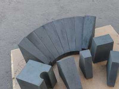
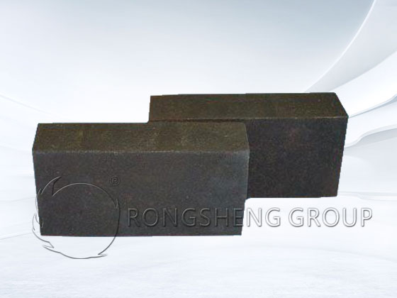
The refractory lining in the cylindrical shell section consists of four layers, arranged from the interior outward: a hot-face refractory brick layer—specifically, high-chrome refractory material that interacts directly with the process gas and molten slag generated by the gasification reaction; a layer of chrome-corundum bricks, positioned immediately adjacent to the outer side of the hot-face refractory layer; a layer of alumina hollow-sphere bricks; and a layer of refractory fiber plastic refractory, which serves to fill the space between the alumina hollow-sphere bricks and the steel shell of the gasifier cylinder.
Conical Section
The refractory lining in the conical section consists of two layers, arranged from the interior outward: a hot-face layer composed of high-chrome bricks; and a layer of chrome-corundum castable positioned between the high-chrome bricks and the conical furnace shell. This castable material is primarily utilized to fill the irregular void spaces situated behind the hot-face refractory bricks.
Material Selection and Masonry Requirements for Refractory Linings
When selecting raw materials for the hot-face bricks (facing the heat source), high-quality materials with a high Cr₂O₃ content must be utilized. The resulting hot-face refractory bricks must meet specific densification standards, exhibiting low porosity, a fine-grained microstructure, and a high bulk density. Furthermore, they must demonstrate exceptional resistance to slag corrosion and superior chemical stability at high temperatures to ensure the overall quality of the refractory lining.
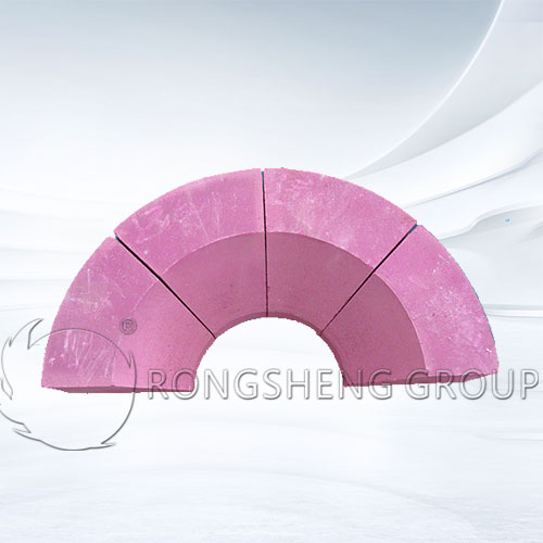
For the back-side lining of the hot-face bricks in the dome and conical sections, chrome-alumina castables should be employed; these materials must possess superior strength, density, and effective insulating properties. During the furnace heat-up phase, this configuration facilitates the formation of a monolithic furnace roof structure, thereby preventing localized overheating and mitigating the risk of “narrow-gas” phenomena (localized flow constriction).
During the masonry construction of the gasifier, refractory expansion joints must be provided in accordance with specified requirements, and all technical parameters—particularly those pertaining to the dome and cylindrical sections—must be strictly adhered to.
The primary technical specifications for refractory brick masonry are as follows: horizontal joints must be <1.0 mm, vertical joints <1.8 mm, vertical alignment (plumbness) within ±5 mm, horizontal alignment (levelness) within ±4 mm, and concentricity within ±5 mm.
Given the unique nature of the reaction media and process conditions within the gasifier, the refractory lining—including expansion joints, nozzle ports, temperature measurement ports, pressure measurement ports, and brick-support areas—requires meticulous design and specialized treatment to ensure the safe, reliable, and long-term operation of the gasifier.
During the masonry process, a specific clearance must be maintained between adjacent refractory lining sections. This intermediate gap should be filled with compressible refractory fiber or plastic refractory material to ensure that adjacent lining sections remain free from compressive stress—and are able to undergo relatively free differential movement—during high-temperature thermal expansion. Additionally, the gaps between adjacent refractory lining sections should be lined with an organic film separator. The joints between hot-face bricks (or those in the insulating/thermal-retention layers) and their immediate lateral neighbors must not form continuous straight lines in the longitudinal direction. Furthermore, the corresponding vertical and horizontal joints across the various layers of the refractory lining—from the innermost hot-face layer outward—must not align to form continuous straight lines that traverse the entire lining structure. The precision of the refractory brickwork at the process burner location must be strictly controlled in accordance with technical specifications. The centerline and concentricity of the process burner must be aligned with the centerline of the furnace body, with a permissible deviation of no more than ±2 mm. The diameter deviation at any given cross-section shall not exceed ±6 mm; the straightness deviation of the furnace lining centerline shall be within ±3 mm; and the total height deviation shall not exceed ±6 mm.
Waterproofing measures must be applied to the interface between the refractory bricks and the castable material to prevent the bricks from absorbing moisture.

Gasifier Bake-out
Upon completion of refractory brick masonry, the structure must undergo natural ventilation and drying for 2 to 3 days. For newly laid refractory bricks, the initial temperature rise—the “bake-out” process—must strictly adhere to the original prescribed heating curve. This process serves to eliminate free water, crystalline water, and residual chemically bound water present within the refractory bricks and mortar. During the bake-out, improper operation or failure to follow the heating curve can lead to cracking of the refractory lining, a reduction in its structural strength, or even spalling (flaking) of the lining material.
If material charging is to commence immediately after the bake-out, the temperature may be raised from 800°C to the designated charging temperature at a heating rate of less than 50 K/h. If, however, the gasifier requires cooling to ambient temperature after the bake-out, the cooling process must not be abrupt; the rate of temperature decrease should be controlled at no more than 20 K/h. When initiating the bake-out by ignition, one must strictly avoid raising the furnace temperature too rapidly, as this risks cracking the furnace lining. The bake-out procedure must be conducted in strict accordance with operational protocols; specifically, the temperature differential between the upper and lower sections of the gasifier’s combustion chamber must be maintained below 80 K. Should an excessive temperature differential arise, it can be corrected by increasing the induced draft volume to adjust the furnace’s negative pressure, thereby elongating the flame and effectively controlling the temperature distribution. In the event of a flameout, the fuel supply must be immediately cut off, and negative pressure (draft) maintained for 5 minutes. Once analysis confirms that the concentration of combustible gases within the combustion chamber is within safe limits, re-ignition may proceed according to operational protocols. The furnace temperature should be raised at a rate of no more than 30 K/h until it reaches the temperature recorded just prior to the flameout, after which heating should continue in accordance with the prescribed heating curve. Upon completion of the gasifier bake-out, the internal furnace temperature should be measured using a temperature gun; the water supply to the quench ring may be shut off—allowing the furnace to cool naturally—only when the internal temperature has dropped below 140°C.
During a standard bake-out procedure, a heating rate of 40 to 50 K/h is required. The temperature is to be raised to the specified target of 1250°C, followed by a period of constant-temperature holding. Throughout the heating phase, raising the temperature too rapidly is strictly prohibited; furthermore, precautions must be taken to prevent excessive temperatures that could lead to slag accumulation and blockage of the slag tap. In the event of a flameout, immediately close the fuel control valve and the shut-off valve. After fully opening the preheating burner damper and maintaining a negative pressure draft for 5 minutes, reignite the burner. Then, increase the temperature at a rate of less than 50 K/h until the temperature prior to the flameout is reached; only then may the temperature be raised to the charging temperature in accordance with the prescribed heating rate.
The Impact of Process Operations on Furnace Bricks and Measures to Extend Their Service Life
Refractory bricks—particularly those on the hot face—experience wear during operation primarily due to mechanical erosion by coal ash and slag, spalling caused by thermal and chemical stresses, chemical corrosion, high-temperature ablation, and gradual thinning resulting from normal use. This section analyzes the actual operational conditions of refractory bricks.
An analysis of the multifaceted forms of wear experienced by refractory bricks—specifically those on the hot face—during operation reveals the following:
- (1) Mechanical Erosion: Molten ash and slag flow across and erode the furnace bricks, leading to severe scouring, deformation, and even detachment of the bricks, often exacerbated by thermal stresses.
- (2) Thermal Stress Spalling: Thermal expansion generates circumferential stresses within the hot-face bricks; this causes creep deformation in the refractory material on the hot-face side, subsequently leading to crack formation and spalling.
- (3) Joint Erosion: When the gaps between refractory bricks are excessively wide, the refractory mortar within the joints shrinks. Consequently, these gaps become vulnerable to erosion by flowing ash and slag, as well as corrosion and ablation by high-temperature gases. The refractory bricks are gradually eroded—starting from these weak joint areas—resulting in “groove-like” or “pitted” forms of damage.
- (4) Impact of Oxygen-to-Coal Ratio: An excessively high oxygen-to-coal ratio prevents the formation of a protective slag layer on the surface of the furnace bricks, thereby negating the “slag-against-slag” protective effect.
- (5) Chemical Corrosion by Ash and Slag: Various elements present in the ash and slag react with different parts of the refractory bricks, thereby corroding them. For instance, K and Na tend to accumulate and react on the surface; Al and Fe react at the interface; while Ca and Si react within the interior of the brick structure.
- (6) Impact of Coal Type: Different types of coal exhibit distinct viscosity-temperature characteristics. Consequently, the corrosive and penetrative effects of the various constituents within the ash and slag on the refractory bricks also vary. Notably, SiO₂ and CaO possess stronger corrosive potential toward refractory bricks than do FeO and Al₂O₃; therefore, changes in the type of coal utilized have a profound impact on the service life of the bricks.
The interior of the gasifier is dominated by reducing gases—specifically H₂ and CO—meaning that the entire hot-face lining of the refractory structure is in constant contact with these reducing gases. Gases permeate into the interior of the refractory bricks through pores or cracks, reacting with the silicon (Si) and iron (Fe) present within the bricks; this reaction causes the cracks to widen, thereby damaging the structural integrity of the bricks.
During the frequent start-up and shutdown cycles of a gasifier, the furnace chamber’s temperature and pressure undergo drastic fluctuations. During the feeding process, the sudden ignition of the coal slurry leads to a rapid surge in gas volume, subjecting the furnace bricks to significant thermal and mechanical shock. Furthermore, frequent adjustments to the operational load—whether increasing or decreasing it—impose similar stresses on the furnace bricks. When the quality of the coal feedstock is unstable, frequent adjustments to the oxygen-to-coal ratio become necessary. An excessively high oxygen-to-coal ratio can result in an abnormal elevation of chromium levels within the furnace slag. In the event of system anomalies—such as a sudden and drastic rise or fall in pressure—the service life and performance of the refractory bricks are significantly compromised.
Following a gasifier shutdown, when the process burner is being extracted, the rate of temperature decline must be strictly controlled. This control can be achieved by covering the furnace opening with a lid to facilitate a slow, “smothered” cooling process, while simultaneously utilizing an induced draft fan to regulate the negative pressure within the chamber.
The refractory bricks situated in different sections of the gasifier exhibit distinct wear characteristics during operation. Generally, the bricks in the furnace dome (arch) demonstrate a lower rate of erosion and enjoy a longer service life. However, during prolonged periods of low-load operation—or when the volatile matter content of the coal is excessively high—the operational conditions for the dome bricks deteriorate, making them highly susceptible to issues such as spalling (detachment) and cracking. If the process burner is poorly designed, or if the gasifier is operated beyond its rated capacity—resulting in an excessively high velocity of oxygen flow into the furnace—the erosive scouring of the bricks on the hot face (the surface exposed to the flame) is significantly exacerbated. The combustion reaction between the excess oxygen and the coal slurry releases a massive amount of heat, causing the dome to remain under extreme thermal stress for extended periods, thereby accelerating the thermal erosion of the dome bricks. Following the installation of the gasifier’s process burner, a significant annular gap often remains between the burner’s outer diameter and the furnace opening. During the initial stages of feeding, this gap facilitates the formation of intense gas vortices within the dome area; these vortices channel high-temperature gases toward the furnace head, causing the large flange at the furnace head to overheat. This overheating compromises equipment safety and adversely affects the service life of both the furnace-opening bricks and the dome bricks. As operational time accumulates, fly ash or coal slag gradually fills this gap; the resulting reduction in the gap size attenuates the vortex phenomenon, allowing the temperature of the large flange at the furnace head to return to normal levels. To mitigate this issue, measures can be implemented—such as encasing the outer diameter of the burner with castable refractory material or wrapping it with refractory fiber insulation—to effectively reduce the gap between the process burner’s outer surface and the furnace opening. The barrel bricks are significantly influenced by the central oxygen flow, coal ash content, and gasifier load; their erosion rate falls between that of the dome bricks and the cone-bottom bricks. If burner misalignment occurs during operation, or if the gasifier’s concentricity deviates from the controlled range, high operating temperatures can lead to severe localized or generalized erosion, thereby compromising the overall service life of the barrel bricks. The cone-bottom bricks exhibit the highest erosion rate—particularly the slag-tap bricks. In the cone-bottom channel, where the cross-sectional area narrows abruptly and flow velocity increases, the volume of molten ash slag contacting the refractory bricks per unit of time is significantly higher; consequently, erosive wear is most severe in this region, necessitating the highest frequency of replacement. The actual service duration of refractory bricks in various sections of the gasifier is heavily dependent on the specific production conditions and operational practices of each facility, resulting in considerable variations in service life. The extent of refractory damage can be assessed and diagnosed by analyzing the chromium content in the coarse slag; a higher chromium content indicates more severe erosive wear.
Furnace temperature can be inferred by analyzing parameters such as the particle size of discharged coarse slag, the extent of slag stringing, the residual carbon content in fine slag, and the composition of process gas (specifically, the content of effective gas components and methane). Where conditions permit, the furnace chamber temperature can be monitored directly; however, thermometers installed in a molten environment are prone to damage due to erosion by slag and gas flows. Additionally, after a scheduled shutdown, the wear on the furnace lining can be measured and evaluated to facilitate adjustments to process operating conditions, thereby ensuring the stable performance of the refractory bricks.
The precision of equipment installation also significantly impacts the furnace lining. Factors such as the vertical alignment of the gasifier vessel, the levelness of the large flange at the gasifier mouth, the concentricity between the process burner and the gasifier, and the concentricity between the burner’s large flange and the furnace mouth all directly determine whether the burner nozzle experiences off-center spraying during operation.
During normal operation, inspections conducted after each shutdown require the replacement of the furnace lining whenever the overall hot-face brick thickness is found to have diminished to one-third of its original design thickness; this measure prevents the furnace wall from overheating during subsequent operation. The hot-face bricks within the cylindrical section typically suffer from severe localized erosion and corrosion—particularly in the vicinity of the furnace chamber thermometer—rendering them unfit for continued use. However, if the surface condition and thickness of the bricks across a large area remain suitable for continued operation, localized patching and repair techniques can be employed to extend the overall service life of the hot-face lining. The bricks within the conical section are categorized numerically from #1 to #9, starting from the slag tap and extending toward the furnace wall; typically, the bricks most severely affected by erosion and corrosion are those located near the slag tap (bricks #1 through #4). By selectively replacing specific rings of bricks based on their individual condition, the overall service life of the entire conical lining can be effectively extended.
Most existing domestic production facilities prioritize economic efficiency, leading to a continuous drive to increase production output and operational load. Furthermore, newly constructed facilities are trending toward larger scales, resulting in ever-increasing coal feed rates. Under the combined influence of complex coal quality, high ash content, variable slag compositions, and high ash fusion temperatures, the refractory lining is subjected to intensified erosion, corrosion, and slag penetration, consequently shortening the service life of the refractory bricks. Consequently, overcoming the technical challenges associated with refractory materials—and thereby enabling long-duration, continuous operation—has emerged as a central focus of attention within the industry.
Extending the Service Life of Refractory Bricks in Gasifier Linings
Within a coal-water slurry gasifier, coal undergoes combustion reactions at operating temperatures exceeding the ash melting point. The resulting slag assumes a molten, liquid state, flowing downward along the inner walls of the furnace chamber and exiting through the slag tap. Should the furnace bricks or other refractory materials suffer any failure—such as gas channeling, brick dislodgment, or structural damage—localized overheating of the furnace’s steel shell may ensue. This, in turn, can trigger unplanned shutdowns and even pose safety risks involving potential equipment damage. Consequently, the service life of refractory bricks is primarily governed by factors such as material selection, furnace construction, kiln drying, startup and shutdown procedures, load adjustments, post-shutdown cooling protocols, and operator handling practices.
Currently, numerous domestic manufacturers are engaged in the development of refractory materials. Through continuous optimization of both refractory brick compositions and manufacturing processes, product quality has been significantly enhanced and reliably assured. Against the backdrop of fierce competition among peer enterprises—all striving to achieve “energy conservation and consumption reduction” as well as “safe, stable, high-capacity, and optimized operations”—extending the service life of refractory bricks has emerged as a central focus of shared interest among users and a critical direction for ongoing research.


