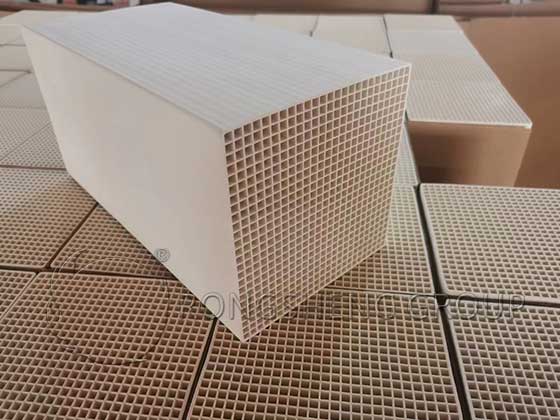
Why the Service Life of Honeycomb Ceramic Heat Storage Bodies Not Long?

What are the reasons? Why the service life of honeycomb ceramic heat storage bodies not long? At present, the service life of honeycomb ceramic heat storage bodies is not very long. The main problems that occur during use are melting, softening, rupture, blockage, and corrosion. There are special cases where a large amount of fragmentation occurs after only one week of use, and there are also those whose service life reaches 2 years due to the large heating capacity or the low service temperature. However, the service life of most heat storage heating furnaces is generally 8-12 months, and the average life is generally short. Common reasons for damage to the honeycomb ceramic heat storage body and short lifespan are analyzed as follows:
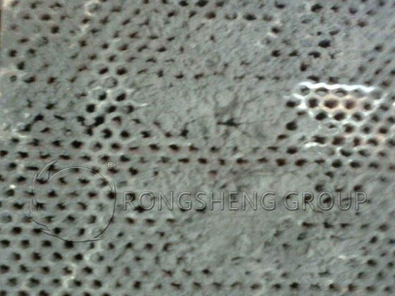
Honeycomb Ceramic Heat-Storage Material

Free Quote

    Free Quote

    Your Name (required)


    Your Email (required)

    Your Phone

    Required Products (required)

    Enquiry Information

    1. Small hole blockage

    Blockage of small holes is one of the most common causes of damage to the honeycomb ceramic heat storage body. After the small holes of honeycomb ceramic heat storage bodies are blocked, it not only directly causes a significant reduction in its heat storage and smoke exhaust performance. It also causes uneven smoke exhaust and heat exposure of the honeycomb ceramic heat storage, which can easily cause cracks and aggravate its damage.

    The Small Holes of Honeycomb Ceramic are Blocked
    The Small Holes of Honeycomb Ceramic are Blocked
    1. Low load softening temperature

    If the load softening temperature is low, during long-term use in normal high temperature environments or when abnormal high temperature occurs, the lower honeycomb ceramic heat storage body will not be able to withstand the combined effect of high temperature and load, and will soften, compressive deformation. This causes the row of honeycomb ceramic heat storage bodies to collapse, and even causes the adjacent honeycomb ceramic heat storage bodies to collapse together, resulting in the blockage of the lower heat storage chamber. The upper part forms a high-temperature channel gap without honeycomb ceramic heat storage body, and the high-temperature flue gas is directly discharged. The heat in the flue gas cannot be effectively recycled, the smoke exhaust temperature is high and the heating capacity is significantly reduced.

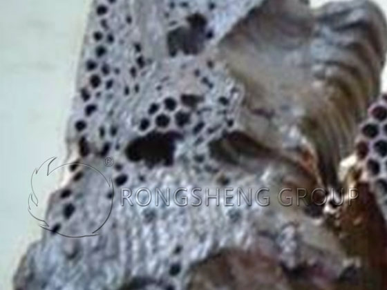
    1. Local high temperature and secondary combustion

    Under normal circumstances, although the furnace temperature exhaust gas exhaust temperature does not exceed 1300℃, the combustion temperature of the flame is much higher. According to the fuel combustion temperature calculation, when the blast furnace gas is preheated to 1000℃, its flame combustion temperature can reach 2400℃. The flame combustion temperature of high-calorie gas fuels, such as natural gas and acetylene, can be as high as 3000℃. Therefore, when secondary combustion or local high temperature channels appear in the heat storage chamber, the temperature it receives has exceeded the load softening temperature and the refractory tolerance limit. The honeycomb ceramic heat storage body will naturally soften, even shrink holes, or severe ablation into clusters.

    The honeycomb ceramic heat storage body ablation into clusters
    The honeycomb ceramic heat storage body ablation into clusters
    1. Poor corrosion resistance and poor slag resistance

    The honeycomb ceramic heat storage body near the first row of the high temperature side reacts with the molten iron oxide or iron oxide small particles brought by the flue gas. The crystal phase inside the honeycomb ceramic heat storage body changes, causing the refractory resistance, load softening temperature, and slag resistance to a sharp decline. Adhesion, shrinkage, blockage or even collapse occurs between each other.

    1. Poor ability to withstand cold and heat

    Due to the frequent heat storage and heat release of honeycomb ceramic heat storage bodies, the temperature changes are severe, causing the walls of the honeycomb ceramic heat storage bodies to be subjected to tensile and extrusion stress alternately. And cracks are generated by the action of thermal stress, and severe fractures will occur. At the same time, collapse will also occur, resulting in the blockage of the lower part of the honeycomb ceramic heat storage body and a hollow space on the upper part, which cannot be used normally. Therefore, the working characteristics of the honeycomb ceramic heat storage body with frequent changes in heat force are the main reasons for its shorter life.

    1. Poor volume stability at high temperature and large deformation of refiring

    During use, most honeycomb ceramic heat storage bodies are installed in cold state and used in hot state. Since the honeycomb ceramic heat storage body has poor high temperature volume stability and large refiring deformation and shrinkage, a gap without honeycomb ceramic heat storage body will be formed on the upper part of the heat storage chamber during use. At this time, the honeycomb ceramic heat storage body itself is not damaged, but most of the flue gas slips directly from the upper gap and gradually forms a high-temperature channel in the upper part of the heat storage chamber. The high temperature causes the nearby honeycomb ceramic heat storage body to rupture, and the channel further expands, thereby accelerating the rupture and damage of the honeycomb ceramic heat storage body.

    1. Biased flow problem

    In the heat storage chamber, the heat exchange process is roughly as follows: in the exhaust stage, when the flue gas flows through the honeycomb ceramic heat storage body, the sensible heat is stored in the honeycomb ceramic heat storage body, heating the honeycomb ceramic heat storage body. In the combustion stage, the air (or gas) is heated when it flows through the honeycomb ceramic heat storage body, and the residual heat is brought back to the furnace. In any of the above stages, if the gas has a biased flow in the heat storage chamber, after several reversals, it is easy to cause local high temperature of the honeycomb ceramic heat storage body and generate thermal stress. When the temperature stress generated exceeds its tolerance limit, the honeycomb ceramic heat storage body will break.

    1. Fire barrier brick problem

    The fire barrier brick plays a dual role of fixing and fire barrier protection for the honeycomb ceramic heat storage body, so it also has an important impact on the service life of the honeycomb ceramic heat storage body. If the material selection or shape and size design of the fire barrier brick is improper, there will be problems such as low brick strength or excessive gap, which will cause the honeycomb ceramic heat storage body to directly contact the flame or secondary combustion. As a result, the honeycomb ceramic heat storage body is prone to rupture, collapse, melting, softening and other problems.

    1. Influence of water vapor in gas pipeline

    When a large amount of condensed water is precipitated from the end of the gas pipeline and enters the heat storage chamber, or when the cooling water pipe in the furnace breaks and flows into the heat storage chamber along the furnace wall, the heat storage body in a high temperature state is very easy to break when encountering liquid water. At the same time, when water enters the heat storage chamber, the viscosity of dust impurities in the fuel gas and iron oxide powder in the flue gas increases, and chemical changes occur, increasing the corrosiveness of impurities. Therefore, it is easy to cause blockage and corrosion of the honeycomb ceramic heat storage body, which accelerates the shortening of the service life of the honeycomb ceramic heat storage body.

      Get Free Quote

      Your Name (required)

      Your Email (required)

      Your Phone

      Required Products (required)

      Enquiry Information

      Composition and Structure of Refractory Materials for Industrial Furnace Lining

      Although there are many types of industrial furnaces, in terms of basic structure, they mainly include three parts:

      • ① Heating system: including equipment systems that provide various heat sources to the materials in the industrial furnace. Such as: energy medium pipelines and equipment systems, power transmission system transformer equipment, etc.
      • ② Industrial furnace body: This is the basic structure of the industrial furnace. Generally includes frame support structure, furnace structure, material conveying system, etc.
      • ③ Smoke exhaust system: mainly includes flue, chimney, heat exchanger, and smoke exhaust auxiliary equipment etc.
      • ④ Other supporting equipment.

      Design of Industrial Furnace Lining Structure

      The basis for completing the furnace construction material to the furnace lining structure when designing the industrial furnace furnace lining structure is a key procedure for achieving the purpose of the equipment process. kiln brick lining. Here, we mainly introduce the furnace lining structure with refractory materials as the main material. During the design process of furnace lining, the following aspects are usually needed:

      • (1) Reasonable furnace size. This is determined by the production process served by industrial furnaces, and the furnace size is subject to process requirements and the overall design of the equipment. The furnace size is the basic condition for the industrial furnace production process. The rationality of the furnace lining size directly affects the production of the entire process.
      • (2) Stable structural form. Due to the special purpose of industrial furnaces, the furnace lining is generally heated on one side. When the furnace lining is in such extreme temperature difference environment for a long time, it may cause structural damage, stress deformation, or form a melting state on the hot surface, the furnace lining structure will be greatly tested. Therefore, the stability of the furnace lining structure is a key indicator of the furnace lining design.
      • (3) Economic and effective material allocation.
      Rongsheng Refractory Lining Cases
      Rongsheng Refractory Lining Cases

      Free Quote

        Free Quote

        Your Name (required)


        Your Email (required)

        Your Phone

        Required Products (required)

        Enquiry Information

        Inner Lining Structure of Industrial Furnace

        Generally speaking, there are four main forms of the inner lining structure of industrial furnaces:

        • (1) Refractory brick lining.
        • (2) Amorphous refractory lining.
        • (3) Refractory ceramic fiber lining.
        • (4) Mix lining.

        Refractory Brick Masonry

        Refractory brick masonry is composed of refractory bricks and refractory mud. kiln brick lining is the most traditional and widely used masonry structure in industrial furnace body structure. When constructing or building an industrial furnace body structure with refractory bricks, first of all, refractory bricks and refractory mud should be selected according to the design or original structural requirements. Then the masonry structure is constructed according to the design drawings. Generally, masonry with refractory bricks is mainly used in the walls, furnace tops, furnace bottoms and pipelines in industrial furnace body structures.

        Amorphous Refractory Lining

        The so-called amorphous refractory lining means that the main material that constitutes the furnace lining lining is an amorphous refractory material. These amorphous refractory materials mainly include: refractory castables, refractory plastics, refractory spray coatings, etc.

        When refractory castable is the main material of the furnace body structure, it is used for working layers such as the side walls, furnace tops, pipeline linings and outer bandages of the furnace body structure. It is also used as an insulation layer between the working layer and the furnace steel structure (such as the furnace shell).

        Refractory plastic: In theory, refractory plastic can replace the function of refractory bricks on the main structure of various industrial furnaces. However, in practical application, you still need to study the following issues before making a decision.

        • ① Type and form of furnace: is it a smelting furnace, reactor or heating furnace;
        • ② Furnace structure: furnace top, side wall or bottom; construction thickness, whether there is heat insulation material; height and load condition of the furnace wall, etc.;
        • ③ Operation status of the furnace: furnace temperature and its changes, whether the operation method is continuous or intermittent, whether the heated material is solid or liquid or gas, impact load in the furnace, etc.;
        • ④Economics and construction conditions, etc. In actual industrial furnace furnace structures, refractory plastics are most commonly used in the furnace roof and furnace wall parts of the furnace body.

        Refractory spray coating: Because spraying tools have the advantages of being able to be at any angle, anywhere, and forming any geometric shape. Therefore, in the furnace lining design of industrial furnaces, a lining formed by spray coating is often used.

        Since the characteristics of spray coatings are basically the same as those of castables, they are also similar to those of castables in structural form. Its application parts in industrial furnace bodies include furnace walls, furnace tops, pipeline lining walls, thermal insulation layers, etc. In order to stabilize the structure of the spray coating lining, different forms of metal anchors or anchor bricks are usually provided in the lining according to specific structural requirements.

        Refractory Ceramic Fiber Lining

        Refractory ceramic fibers are loose as a semi-finished raw material and can be processed into finished products such as fiber blankets, fiber ropes, fiber paper, fiber boards, fiber fast-tipping (folding modules or laminated modules). After adding the binder, it can be used as a fiber spray coating or fiber castable. Ceramic fibers can be used directly in a loose shape. However, when it exists as a lining, ceramic fibers are often processed into blankets, plates, or blocks for use.

        Therefore, in the lining of existing industrial kilns, it is essentially determined that refractory materials must be used to protect the melting changes of the shell. Based on the actual working conditions of each industrial kiln, a mixed body structure of a variety of refractory materials is generally used to extend the life of the furnace lining and save production costs for enterprises.

          Get Free Quote

          Your Name (required)

          Your Email (required)

          Your Phone

          Required Products (required)

          Enquiry Information