Refractory Materials for Aacid Slag-Based Electric Arc Furnace Linings
In the high-temperature smelting process of an electric arc furnace with intense charge movement, the refractory lining of the furnace is an essential guarantee for the normal operation of the process. Based on the type of slag and the properties of the refractory materials used, electric arc furnaces can be divided into acidic slag electric arc furnaces and basic slag electric arc furnaces. Most of the aforementioned electric arc furnaces used in steelmaking are basic slag electric arc furnaces, with a slag basicity greater than 1. Since acidic slag does not have desulfurization and dephosphorization effects, the application of acidic slag electric arc furnaces is currently limited in my country. Currently, the furnace linings mostly use basic refractories with good resistance to basic slag, such as magnesia-carbon bricks and magnesia-chrome bricks. Therefore, my country produces a very large amount of basic slag as a byproduct each year. It is estimated that in 2019, the slag produced in my country’s electric arc furnace steelmaking production was approximately 0.2 billion tons. Such a large accumulation of slag, if not properly handled, could cause environmental pollution due to the heavy metals such as chromium, lead, and cadmium it contains, posing a significant potential threat to biological health and the balance of the ecological environment.

Refractory Materials for Lining Acidic Slag-Based Electric Arc Furnaces
The slag in acidic slag-based electric arc furnaces is acidic, and the lining uses acidic or neutral refractory materials. Compared to basic slag, acidic slag is more environmentally friendly. When the SiO2 content in acidic slag is high, it forms acidic silicate slag with a microstructure similar to glass. This is an amorphous, non-crystallizing material that cools slowly, i.e., glassy slag (hereinafter referred to as “glass slag”). Some studies suggest that when amorphous silicate materials are corroded in an acidic environment, the inconsistent dissolution of oxides causes the silicate surface to form a silicon-rich protective layer. This fixes harmful metals in the slag, and the higher the degree of vitrification (amorphous material content), the better the fixation effect. This significantly reduces the risk of environmental pollution and harm to animal and plant health. Based on this characteristic, many industrial waste treatment processes, such as leather industry waste treatment and waste incineration fly ash treatment, are suitable for this high-temperature vitrification process, which is an effective method for fixing metal pollutants. Meanwhile, this glass slag can also be reused as a raw material for preparing microcrystalline glass. The vitrification process of acidic slag has been proven to be a successful example of the harmless treatment and reuse of waste resources.
Acidic slag-based electric arc furnace smelting can be used for the recovery and harmless treatment of valuable metals in secondary resources. One very important smelting process is the electric arc furnace smelting of waste automotive exhaust purification catalysts. Waste automotive exhaust purification catalysts mainly consist of a carrier component (composed of oxides such as γ-Al₂O₃ or cordierite) and an active component (composed of three precious metals: platinum, palladium, and rhodium). After crushing and finely grinding the catalyst, it is mixed with trapping metals, flux, and a small amount of coke, granulated, and then smelted in an electric arc furnace. This utilizes the principle that trapping metals such as iron or copper have a strong affinity for platinum group metals in the catalyst at high temperatures (above 1420 °C). This process enriches the precious metal active components in the catalyst within the molten metal, while the catalyst support components, along with added fluxes such as SiO2 and CaO, form slag that enters the glass slag, achieving efficient and harmless recovery of valuable metal resources. Depending on the attractant and flux composition, the electric arc furnace operates at varying temperatures, reaching up to 1600 °C. At this temperature, the scouring motion of the furnace charge on the refractory material is quite intense. Furthermore, carbon is added during smelting to reduce the oxides of the target metal, creating a reducing atmosphere in the furnace, thus placing high performance requirements on the furnace lining refractory material of the electric arc furnace. Existing refractory materials have a short service life in the aforementioned electric arc furnaces; in pilot-scale small electric arc furnaces, the lining needs to be replaced approximately every two months, limiting the industrial application of this process. This paper addresses the problem of short lining service life in electric arc furnace smelting of acidic slag-based refractory materials, analyzing the mechanism of acidic glass slag corrosion of refractory materials. It also reviews the development and research of refractory materials suitable for high-temperature acidic slag-based electric arc furnaces both domestically and internationally in recent years. The feasibility of these materials in high-temperature acidic slag-based electric arc furnaces was analyzed, and the future development trend of refractory materials for acidic slag-based smelting furnaces was prospected.
The Corrosion Mechanism of Acidic Glass Slag on Refractory Materials
The corrosion of refractory materials by molten slag is a complex process involving many influencing factors. These include the chemical composition and pH of the molten slag and refractory materials, the viscosity and surface properties of the molten slag, the melting atmosphere, the physical properties of the refractory materials (porosity, high-temperature flexural strength, etc.), and the solubility limits of their components in the molten slag (i.e., the concentration of refractory components in the molten slag at saturation). Furthermore, unlike other melting furnaces, electric arc furnaces use a high-temperature electric arc to heat the furnace charge, and the resulting electromagnetic field significantly affects the properties of the molten slag. For example, it alters the wettability and penetration kinetics of the molten slag on refractory materials, influencing the formation and distribution of different phases, thus affecting the erosion of refractory materials by the molten slag. Currently, there is little research, both domestically and internationally, on the influence of the electromagnetic field of electric arc furnaces on the erosion of refractory materials by acidic glassy molten slag. The erosion of refractory materials by glass slag can be divided into two types: penetration erosion and chemical corrosion.
Current Status of Research on Refractory Materials for Acidic Slag-Based Electric Arc Furnaces
Currently, research on the slag erosion resistance of refractory materials largely relies on high-temperature erosion resistance tests to simulate the erosion of refractory materials by molten slag during industrial production, in addition to using refractory materials that have failed in actual industrial production. The quality of refractory material’s slag resistance is evaluated using indicators such as the rate of mass change before and after the test, the erosion rate of the molten slag, and the penetration rate. High-temperature erosion resistance tests can be divided into two types: static and dynamic methods. The difference lies in whether an external force is applied to keep the molten slag flowing relative to the refractory material. The most widely used static method is the static crucible method. This method requires simpler equipment and operation, and the molten slag only statically penetrates and dissolves the refractory material. It is suitable for refractory materials whose erosion is mainly caused by the dissolution of components in the molten slag. Dynamic erosion resistance tests are more suitable for refractory materials with more complex erosion processes.
Application of Refractory Materials in High-Temperature Acidic Slag-Based Electric Arc Furnaces (1600 ℃)
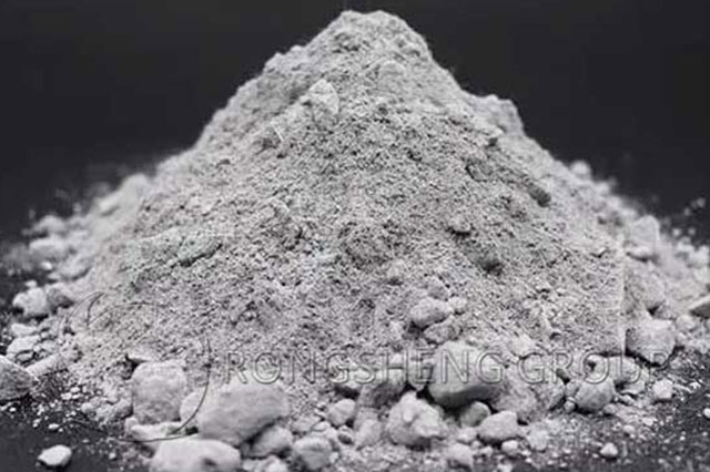
Based on the corrosion mechanism of acidic glassy molten slag (glass slag) on refractory materials, and assuming their potential application in acidic slag-based electric arc furnaces, this paper reviews the research results on the resistance of several refractory materials (Al2O3-SiO2 materials, Al2O3-SiO2-ZrO2 composite materials, chromium-containing materials, densified zirconium (chromium)-containing materials, carbonaceous and carbide materials) to glass slag corrosion, summarizing their advantages and disadvantages. The feasibility of applying these refractory materials in high-temperature acidic slag-based electric arc furnaces (1600 ℃) was discussed, and the following conclusions were drawn:
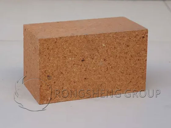
- (1) Al2O3-SiO2 refractory materials have poor high-temperature corrosion resistance and are not suitable for high-temperature acidic slag-based electric arc furnaces.
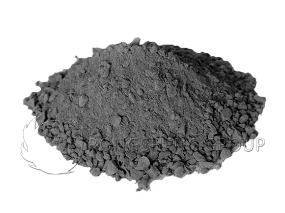
- (2) Chromium-containing refractory materials have excellent resistance to glass slag corrosion, but due to the toxicity of Cr, which can easily cause environmental hazards, their use should not be expanded.
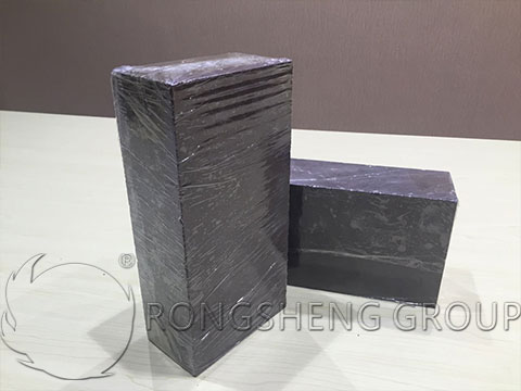
- (3) Carbonaceous and carbide refractories have high thermal conductivity and poor insulation performance, which can lead to a significant increase in energy consumption of electric arc furnaces.
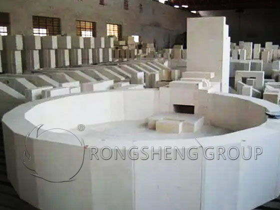
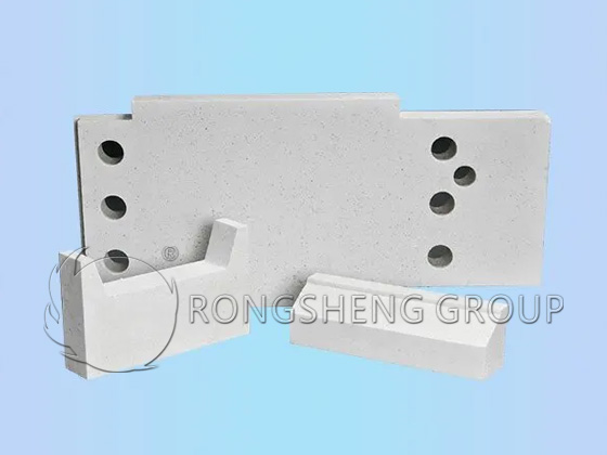
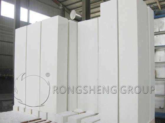
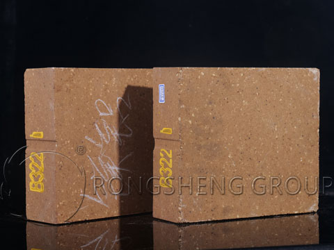
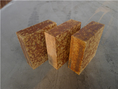
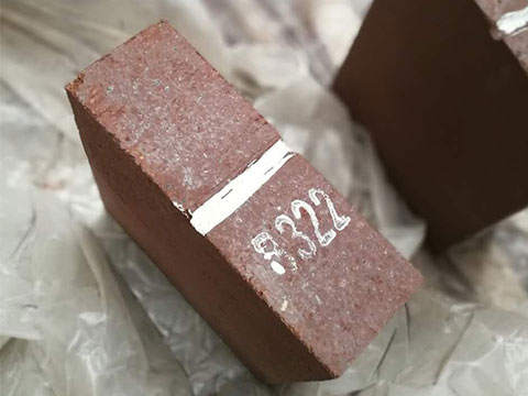
- (4) Al2O3-SiO2-ZrO2 composite refractories have good resistance to glass slag corrosion, and the densification process further enhances their corrosion resistance. In addition, the feasibility of using 41# (containing 41% ZrO2) fused cast zirconia-corundum bricks in high-temperature acidic slag-based electric arc furnaces (1600 ℃) has been preliminarily demonstrated.
Currently, with the gradual increase in public awareness of environmental protection and the strict implementation of national environmental protection policies, researchers will focus on improving and developing environmentally friendly and energy-saving refractory materials without affecting service life. The structure and properties of the slag in high-temperature acidic slag-based electric arc furnaces are similar to those of the glass melt in glass melting furnaces and other vitrification furnaces. The development of refractory materials for high-temperature acidic slag-based electric arc furnaces can fully draw on the industrial application experience of both. It is foreseeable that, represented by 41# fused cast zirconium corundum refractory, densified zirconium-containing materials with excellent resistance to glass melt corrosion will become a widely used furnace lining material for high-temperature acidic slag-based electric arc furnaces.
Buy acidic refractory, acid resistant refractory from Rongsheng Refractory Factory. Please send the email to Rongsheng, and get free solutions and quotes for refractory furnace linings.