Alumina-Silicate Refractory Materials for Rotary Kilns Used in Calcining Magnesia Materials
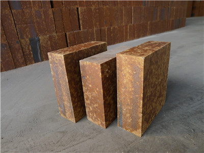
A certain company utilizes a rotary kiln to fire magnesia-based materials with an MgO content of approximately 30%. The kiln’s firing zone spans a length of 20 to 30 meters, with a firing temperature of around 1470°C and a shell surface temperature ranging from 300°C to 310°C. When using high-alumina bricks with a 65–75% alumina content, the service life of the rotary kiln lining is less than 20 days; with 80% high-alumina bricks, the service life extends to only about 30 days. The severe erosion of refractory materials necessitates frequent kiln maintenance, which significantly compromises both product quality and production efficiency. Consequently, the company is seeking non-magnesia refractory materials suitable for rotary kilns, aiming to ensure a service life of at least six months.
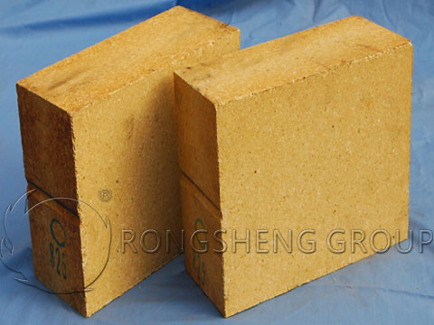
Refractory Materials for Rotary Kilns Used in Calcining Magnesian Materials
Application of the Original 80% High-Alumina Bricks in the Rotary Kiln
The characteristics of the 80% high-alumina bricks after 30 days of service were observed; from the surface of the used bricks, the primary manifestations were severe penetration and corrosion. An analysis was conducted on the physicochemical properties of the high-alumina bricks originally used in this rotary kiln. A static crucible method was employed to perform corrosion resistance tests on the 80% high-alumina bricks. Magnesian material was packed into the test specimens, and the temperature was raised at a specific heating rate to 1500°C. After holding at this temperature for 3 hours, the specimens were allowed to cool naturally within the furnace to room temperature, after which they were cut open along their central axis.

Deterioration of the Original 80% High-Alumina Bricks in the Rotary Kiln
Analysis of the Deterioration Characteristics of the High-Alumina Bricks
Based on the physicochemical properties of the high-alumina bricks, it is evident that the material possesses high porosity, and its initial load-softening temperature is only 1418°C—significantly lower than the operating temperature of 1450–1470°C within the kiln’s firing zone. Consequently, during operation, the refractory material undergoes softening and deformation, leading to accelerated corrosion. Furthermore, an analysis of the bricks’ reheat linear change rate reveals that these 80% high-alumina bricks exhibit a tendency to shrink at high temperatures; this characteristic makes them highly susceptible to the widening of brick joints. Such widening compromises the structural integrity of the kiln shell and accelerates the deterioration of the refractory lining.
Corroborated by the characterization results of the corrosion resistance tests, the surfaces of the specimens appeared loose and porous following the reaction, exhibiting distinct signs of material penetration. This indicates that under high-temperature conditions, a liquid phase continuously forms and permeates through the brick joints, thereby expanding the surface area exposed to corrosion. This process accelerates the rate of deterioration, ultimately leading to a loss of structural integrity in the rotary kiln and a shortened service life.
Analysis of the Deterioration Mechanism of the High-Alumina Bricks
(1) Chemical Corrosion: This rotary kiln is utilized for the production of magnesian materials, which are primarily composed of MgO and SiO₂. Consequently, chemical reactions occur within a binary system dominated by MgO and SiO₂.
During the operation of the kiln, when the raw materials—predominantly MgO and SiO₂—come into contact with the Al-rich refractory lining (i.e., when Al₂O₃ is introduced into the MgO-SiO₂ system), a ternary MgO-SiO₂-Al₂O₃ system is formed. When 2MgO·SiO2 comes into contact with Al2O3, cordierite (2MgO·2Al2O3·5SiO2) begins to form at temperatures exceeding 1250°C; this newly formed cordierite subsequently decomposes and melts at 1460°C. Furthermore, within this ternary system, Al2O3 reacts not only with the MgO component to form MgAl2O4 (spinel) but also with the SiO2 component to form Al6SiO13 (mullite).
The formation of spinel is accompanied by a volume expansion of 5% to 8%. When combined with the liquid-phase melting induced by interfacial reactions, this process leads to the deterioration and damage of the refractory materials, ultimately compromising the overall service life of the kiln.
(2) Mechanical Stress. Rotary kilns are typically inclined at a gradient of 3% to 5%. During the production process, as the kiln rotates at a specific speed, the internal refractory lining is subjected to various forces: it experiences inertial forces that induce a tendency toward downward movement, while simultaneously enduring compressive stresses from the kiln shell as well as erosive wear caused by the flow of materials—all of which contribute to the degradation and failure of the refractory lining.

Required Properties for Refractory Materials in Rotary Kilns
Based on the composition of the magnesia-based raw materials being calcined, the operating environment, and the firing temperature—and informed by an analysis of the failure mechanisms observed in high-alumina bricks previously used in such rotary kilns—the refractory materials intended for use in magnesia-calcining rotary kilns must possess specific properties. These include high density, high mechanical strength, and a high refractoriness under load (softening point). Furthermore, they must exhibit excellent resistance to chemical corrosion by the magnesia-based raw materials being processed, as well as favorable kiln lining-forming (coating) characteristics.
Material Selection
In response to client feedback regarding the poor spalling resistance and high cost of traditional magnesia-based refractories—which were deemed unsuitable for the current operational requirements of this specific rotary kiln—this study focused on selecting alternative refractory materials primarily based on the alumina-silica system. Specifically, samples of the following material types were selected for evaluation: mullite-andalusite bricks, high-alumina silicon carbide bricks, special high-alumina bricks, and corundum-spinel bricks. Subsequently, a static crucible test method was employed to analyze and compare their respective corrosion resistance capabilities. In this procedure, the magnesia-based raw material was packed into a cavity within each refractory sample. The samples were then heated at a controlled rate to a peak temperature of 1500°C, held at this temperature for 3 hours, and finally allowed to cool naturally within the furnace back to room temperature. Each sample was then sectioned along its central axis to facilitate a detailed examination of the corrosion resistance exhibited by the different refractory materials against the magnesia-based raw material.
Corrosion Resistance Results and Discussion
Based on the experimental data, the ranking of the materials in terms of corrosion resistance (from highest to lowest) is as follows: Sample #4 > Sample #2 > Sample #3 > Sample #1 > 80% High-Alumina Brick. The ranking in terms of penetration resistance (from highest to lowest) is: Sample #2 > Sample #1 > Sample #3 > 80% High-Alumina Brick > Sample #4.
- (1) Sample #1 consists of a mullite-andalusite composition. At high temperatures, the magnesia-based raw material reacted with the brick, resulting in the formation of a white, flocculent reaction layer on the brick’s surface. This material features a relatively high SiO₂ content; consequently, within the temperature range of 1200°C to 1300°C, an accelerated reaction occurs between the SiO₂, Al₂O₃, and MgO components, leading to the formation of cordierite. As the temperature continues to rise, the newly formed cordierite undergoes decomposition and melting at approximately 1450°C. This process releases a significant amount of supercooled liquid phase, which adheres to the surface of the raw material being processed, thereby causing corrosion of the refractory lining. While the overall corrosion resistance of this material is considered moderate, its high density endows it with excellent resistance to material penetration.
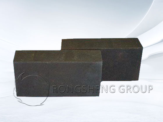
- (2) Sample #2 consists of high-alumina silicon carbide bricks. Following the incorporation of silicon carbide, the SiC on the surface oxidizes to form a dense, protective film of SiO2, which effectively prevents further erosion and infiltration of the brick by the magnesia-based materials. Consequently, this material exhibits superior resistance to both erosion and infiltration.
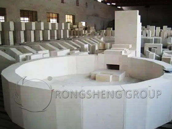
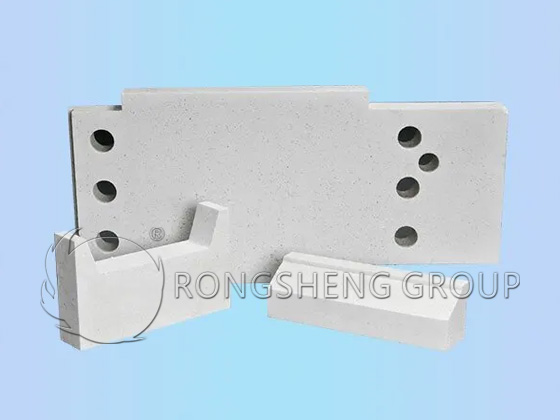
- (3) Sample #3 consists of special high-alumina bricks. The material surface appears white, and signs of erosion and infiltration are minimal; internally, this high-alumina brick develops a composite corundum-mullite phase structure. The mullite phase enhances the compactness of the structural network, thereby improving infiltration resistance. The corundum phase serves to resist erosion; specifically, when the refractory surface reacts with the magnesia-based materials at high temperatures, a molten phase is formed. Upon subsequent crystallization, this material adheres to the refractory surface, creating a structural layer resembling a kiln coating, which effectively prevents further erosive reactions of the refractory. Overall, this material is rated as having good resistance to both erosion and infiltration, while also offering the lowest cost.
- (4) Sample #4 consists of corundum-spinel bricks. While they demonstrate good resistance to erosion, their resistance to infiltration is poor, and their cost is high.
Based on a comprehensive evaluation of the erosion resistance and cost of the four materials, the high-alumina silicon carbide bricks and the special high-alumina bricks were identified as the preferred choices. However, when analyzed from the perspectives of thermal conductivity and cost-effectiveness, the high-alumina silicon carbide bricks possess both higher thermal conductivity and a higher price point than the special high-alumina bricks; therefore, the special high-alumina bricks were ultimately selected. The reaction characteristics observed between the molten magnesia-based materials and the special high-alumina bricks indicate that the latter possesses excellent capability for forming a protective kiln coating.
Performance Optimization of Special High-Alumina Bricks
To better meet the operational demands of rotary kilns used for calcining magnesia-based materials, the specifications and manufacturing processes of special high-alumina bricks have undergone optimization. By optimizing the matrix A/S (Alumina-to-Silica) ratio, a composite corundum-mullite phase structure was generated; the mullite phase enhances the compactness of the structural network, thereby improving resistance to penetration, while the corundum phase serves to resist erosion. The newly optimized special high-alumina bricks exhibit excellent physicochemical properties, along with superior resistance to both erosion and penetration.
Static crucible tests were conducted to analyze the erosion resistance of the optimized special high-alumina bricks, demonstrating their excellent capability to withstand erosion.
Product Application Results
- (1) Monitoring of the special high-alumina bricks in actual customer operations revealed that the rotary kiln has operated continuously for 900 days, representing a significant extension of service life. During this period, no kiln shutdowns for maintenance were necessitated by issues such as erosion, spalling, or brick detachment. Production efficiency and product quality were successfully safeguarded, earning the product high acclaim from the client.
- (2) These special high-alumina bricks possess moderate thermal conductivity and excellent capability for forming a protective kiln coating (clinker coating). The surface temperature of the kiln shell in the firing zone remained at approximately 240°C—a reduction of about 60°C compared to previous operations. On one hand, this prevents plastic deformation of the kiln shell caused by excessive heat, thereby reducing safety risks associated with kiln operation. On the other hand, the reduction in heat loss from the kiln shell surface not only achieves the objective of energy conservation and cost reduction but also improves the working environment at the production site.
- (3) A microscopic analysis was performed on the special high-alumina bricks after 900 days of service. Observations of the reaction layer—magnified 56 times—combined with EDS (Energy-dispersive X-ray spectroscopy) scanning analysis, revealed that the magnesia-based charge material (predominantly composed of Mg and Si at a macroscopic level) had not induced any significant penetration reactions within the special high-alumina bricks.
Further high-magnification analysis of the reaction and erosion layers of the used bricks revealed an enrichment of K and Na elements on the surface of the refractory’s reaction layer. This enrichment resulted in the formation of a protective liquid-phase layer, which effectively prevented further erosion of the refractory material. When the reaction layer was magnified 300 times, the dynamic reaction processes occurring between the refractory material and the magnesia-based raw materials during kiln operation could be clearly observed. Measurements indicated that the thickness of the formed protective liquid-phase layer ranged from approximately 150 to 300 μm. The interior of the refractory material has not suffered erosion or damage from the magnesia-based raw materials; based on an assessment of the current performance of this specialized high-alumina brick, its service life is projected to exceed five years.